How to Choose the Right Current Transformer?
Choosing the right Current Transformer is a measurement decision, not a simple catalog exercise. Modern grids face faster demand growth, distributed generation, and tighter protection requirements. The International Energy Agency’s Electricity 2024 report forecasts global electricity demand growth of about 3.4% annually from 2024 to 2026. More current on networks means more pressure on sensing accuracy.
A Current Transformer must match the primary current, secondary rating, burden, insulation level, and required accuracy class. Protection systems may need a high knee-point voltage to avoid saturation during faults. Metering systems usually prioritize stable accuracy across normal operating loads. IEC 61869-2 defines key requirements for current transformers, while IEEE C57.13 provides widely used accuracy and performance guidance. These standards offer a dependable starting point, but they do not replace site verification.
Small errors matter. A transformer rated for 800 amperes may perform poorly on a feeder that normally carries only 90 amperes. Excessive cable length can also increase secondary burden. That detail is easy to miss during design reviews. Engineers should inspect fault levels, relay requirements, ambient temperature, mounting space, and conductor geometry before ordering. The correct ratio may still be wrong if saturation, polarity, or installation clearance is overlooked. Even experienced teams occasionally treat the datasheet as the whole answer. It is not. This guide explains how to compare specifications, interpret professional standards, and avoid practical selection mistakes. Reliable choices come from calculations, field experience, and careful questioning.

Understanding Current Transformer Types and Their Working Principles
How to Choose the Right Current Transformer?
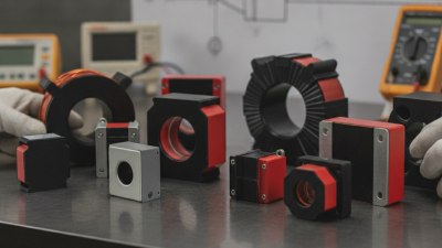
Current transformers work through electromagnetic induction. A primary conductor carries the load current. The magnetic core transfers a proportional current to the secondary winding. Measuring equipment then reads this smaller, safer signal. The main types are wound, bar, and window transformers. Wound types suit lower currents and precise relay applications. Bar types handle high currents in switchgear. Window types fit around existing cables with minimal installation changes.
Selection should begin with the system’s maximum current, voltage, frequency, and required accuracy class. IEC 61869-2 specifies performance requirements for measuring and protection current transformers. Check the burden rating in VA, too. Excessive connected resistance can increase errors and drive the core toward saturation. Protection CTs usually tolerate faults better than metering CTs. They are not interchangeable. Core-balance CTs detect residual current by surrounding all live conductors together. If one conductor is excluded, the reading can become misleading.
Grid expansion makes dependable measurement more important. The IEA’s Electricity 2024 report expects global electricity demand to grow by over 4% in 2024 and 2025. IRENA reported 473 GW of renewable capacity additions in 2023. These systems create more varied current profiles. I would verify harmonics, temperature, and installation space before ordering. I once underestimated cable bending space; the electrical choice was correct, but the cabinet fit was poor. Never open an energized CT secondary. A dangerous voltage can appear. Small details matter.
Selecting the Correct Ratio, Accuracy Class, and Burden Rating
Choosing a current transformer starts with the ratio. Match the primary rating to the highest expected continuous current, not only today’s load. A 600/5 CT on a 180 A feeder may underuse the meter’s resolution. A 200/5 CT could saturate during sustained overloads. Field engineers should review load profiles, motor starting current, and future capacity. The U.S. Energy Information Administration has reported that transmission and distribution losses remain around 5% of electricity delivered in recent years. Small measurement errors still matter across large systems. The ratio deserves careful checking.
Accuracy class must fit the application. IEC 61869-2 defines performance requirements for measuring and protection CTs, while IEEE C57.13 provides widely used U.S. requirements. Classes such as 0.2, 0.5, and 1.0 indicate different measurement limits. Class 0.2 is common for revenue metering; protection circuits need different specifications, such as 5P or 10P. These labels are not interchangeable. A protection CT can perform poorly in precision metering.
Burden rating is the total secondary load, measured in VA. Include the meter, relay, terminal blocks, and cable resistance. A 5 VA instrument connected through long wiring may exceed its rated burden. Then accuracy can collapse. Keep the wiring short. Use the actual cable length. A conservative selection is not automatically a better one. I have seen oversized ratios reduce useful resolution, while neglected burden calculations created avoidable errors. Verify the final choice against IEC 61869-2 test data and the manufacturer’s certified curve.
How to Choose the Right Current Transformer?
Selecting the Correct Ratio, Accuracy Class, and Burden Rating
1. Select the Ratio
Choose a primary rating close to the expected maximum load current. A 5 A secondary CT produces 5 A when the primary current reaches its rated value.
2. Choose Accuracy Class
Metering CTs use defined accuracy classes for measurement performance, while protection CTs use protection classes specified by the applicable standard and system design.
3. Verify Burden
The CT burden must cover the connected meter, relay, terminals, and wiring. Burden is commonly expressed in VA at the rated secondary current.
Chart values are calculated from the nominal CT ratio: secondary current = primary current × 5 ÷ rated primary current. Confirm final ratio, accuracy class, burden, insulation level, and applicable requirements against the installation design and relevant standards such as IEC 61869-2.
Evaluating Installation Methods, Safety Features, and Environmental Limits
Choosing a current transformer starts with the installation method, not the catalog ratio. Solid-core units usually provide better accuracy, but they require conductor disconnection. Split-core units install around an existing cable, reducing downtime, though poor closure can increase measurement error. Keep the conductor centered in the window. It matters.
IEC 61869-2 defines performance requirements for measuring and protection transformers, including accuracy and thermal limits. Select the burden rating after checking cable length, meter input, and terminal resistance. Never leave a CT secondary open while primary current flows. The resulting high voltage can damage insulation and seriously injure workers. Use shorting terminals, clear labels, and a documented isolation procedure aligned with NFPA 70E practices.
Environmental limits deserve equal attention. IEC 60529 IP ratings help assess dust and water exposure, but they do not replace temperature or corrosion reviews. Check the specified operating range, altitude derating, humidity, vibration, and chemical contaminants. The IEA Electricity 2024 report projects global electricity demand to grow by about 3.4% annually through 2026, increasing pressure on monitoring equipment in dense, hotter installations. I have seen technically correct selections fail because enclosure heating was underestimated. A larger enclosure, ventilation, or a higher-temperature class may be necessary. Recheck the assumptions.
Comparing Performance, Certifications, Maintenance, and Total Cost
Choosing a current transformer requires more than checking the ratio and price. Accuracy must remain stable under actual burden, fault current, temperature, and frequency conditions. IEC 61869-2 defines performance requirements for instrument transformers, while IEEE C57.13 specifies accuracy classes and testing methods. Ask for routine-test records, excitation curves, and a clear saturation limit. A small mismatch can distort protection decisions.
Certification reduces uncertainty, but it does not replace field judgment. NETA’s 2023 Maintenance Testing Specifications recommend visual inspection, insulation testing, polarity checks, and secondary-circuit verification. These tests can reveal loose terminals, insulation damage, or an open secondary circuit. The danger is easy to miss. Maintenance intervals should reflect humidity, vibration, switching frequency, and fault exposure, not only calendar dates. In practice, a well-documented test history is often more valuable than a polished certificate.
Total cost includes installation, testing, downtime, energy losses, and replacement risk. The U.S. Department of Energy’s transformer-efficiency analysis projected lifecycle savings of about $12.9 billion from stronger efficiency standards across covered distribution transformers. CTs consume less energy, but their burden and wiring still affect system losses. Compare five- to fifteen-year ownership costs, including access equipment and outage planning. The cheapest unit may become expensive after one difficult inspection. I would still challenge any calculation that ignores labor rates or assumes perfect site conditions. Industry data is useful, but local evidence should decide.