Leave Your Message
Choosing insulation components can seem straightforward until heat, moisture, vibration, or tight clearances affect the design. The right Insulation Parts should suit the equipment’s operating conditions, not just its appearance or price. A sleeve that fits a cable on the workbench may become loose near a connector. A sheet that looks thick enough may compress under a fastener. Small details matter.
Start by checking the expected temperature range, voltage requirements, mechanical loads, and exposure to oils or humidity. Then compare material properties, dimensions, tolerances, and compatibility with nearby components. For electrical applications, confirm that product data matches the intended use; do not assume that one insulation rating covers every condition. Review manufacturer specifications and, when available, test results relevant to your assembly. A qualified engineer can help assess unusual or high-risk operating environments.
Installation deserves the same attention as selection. Sharp edges, tight bends, trapped moisture, and uneven pressure can weaken insulation or shorten service life. Ask how the part will be cut, fitted, secured, and inspected. Keep records of product specifications and any changes made during assembly. Even a careful checklist can miss something. Recheck the actual installation, especially where parts meet or move. Choosing well is a practical process: match evidence to conditions, allow for tolerances, and revisit assumptions when the design changes.
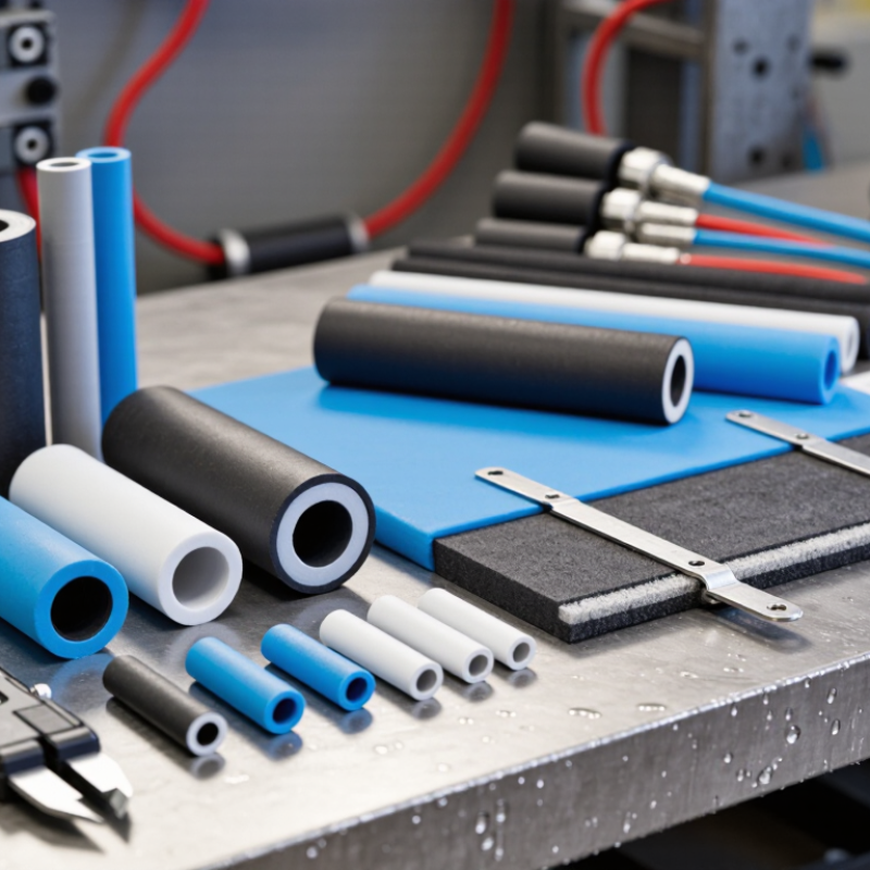
Choosing insulation parts starts with a service map, not a catalog. Record normal and upset temperatures, start-up cycles, and the coldest surface conditions. A brief temperature spike can exceed a material’s rating. Small detail. For wet or chilled lines, specify a continuous vapor retarder and sealed joints; water entry can reduce thermal performance and increase corrosion risk. For hot lines, check jacketing seams and drainage around supports.
Loads matter too. Pipe shoes, vibration, wind, and repeated maintenance can crush soft insulation or open joints. Use load-bearing inserts where supports compress the system, and leave removable sections at valves. The U.S. Department of Energy’s Steam Tip Sheet #2 estimates that 1/8 inch of scale inside a four-inch steam pipe can raise fuel use by 2 percent. That figure concerns scale, not insulation, but it shows why checking the pipe condition belongs in the assessment. A tidy spreadsheet can still miss a leaking valve.
Match the material and assembly to applicable specifications and local requirements. ASTM C547 covers mineral-fiber pipe insulation, while ASTM C680 provides methods for estimating heat loss and surface temperatures. Confirm temperature limits, water resistance, fire performance, and mechanical strength against the actual service. The IEA’s Energy Efficiency 2023 report puts industry at about 37 percent of global energy use, making avoidable thermal losses consequential. One assumption deserves another check: the “standard” operating temperature may not capture cleaning cycles or brief shutdowns.
| How to Choose the Right Insulation Parts? - Map Operating Temperature, Moisture, Loads, and Applicable Standards | |||
|---|---|---|---|
| Design Dimension | What to Map | Selection Guidance | Relevant Standard or Test |
| Operating temperature | Normal continuous temperature, short-duration peaks, temperature cycling, and heat from nearby components. | Choose an insulation system whose thermal class and qualified material ratings cover the expected service conditions. IEC 60085 thermal classes include A (105°C), E (120°C), B (130°C), F (155°C), H (180°C), N (200°C), and R (220°C). These are system classes, not automatic ratings for every individual part. | IEC 60085 — thermal evaluation and classification of electrical insulation systems. Use material-specific datasheets and application qualification for part-level limits. |
| Moisture and humidity | Relative humidity, condensation, washdown, immersion, water exposure, and the time the part remains wet. | Check water absorption, dimensional change, insulation resistance, and dielectric performance after appropriate conditioning. For damp or wet service, validate the complete part and assembly; a low absorption value alone does not establish suitability. | ASTM D570 — water absorption of plastics. IEC 60243-1 — electrical strength of solid insulating materials under specified test conditions. |
| Mechanical loads | Mounting pressure, bending, impact, vibration, fastener torque, and sustained loads at operating temperature. | Compare strength and stiffness at the actual service temperature. Consider creep, cracking at holes or edges, and loss of clamping force over time. Brittle materials may need support that limits impact and tensile stress. | ASTM D790 — flexural properties of plastics. ASTM D695 — compressive properties of rigid plastics. Select test methods appropriate to the material and part geometry. |
| Voltage and dielectric stress | Working voltage, transient overvoltage, electric-field concentration, insulation thickness, and the consequences of breakdown. | Verify dielectric strength and required insulation coordination for the complete design. Do not use a material’s laboratory breakdown value alone as the allowable working voltage of a finished part. | IEC 60243-1 — electric strength testing of solid insulating materials. IEC 60664-1 — insulation coordination for equipment within its stated scope. |
| Creepage and tracking | Surface paths between conductive parts, pollution level, condensation risk, and material resistance to electrical tracking. | Determine creepage requirements from the applicable voltage, pollution degree, and installation conditions. IEC material groups use comparative tracking index (CTI): Group I, CTI ≥ 600; Group II, 400 ≤ CTI < 600; Group IIIa, 175 ≤ CTI < 400; Group IIIb, 100 ≤ CTI < 175. | IEC 60112 — proof and comparative tracking indices. IEC 60664-1 — creepage-distance and insulation-coordination considerations. |
| Chemical and environmental exposure | Contact with oils, cleaning agents, solvents, salt, dust, ultraviolet light, or corrosive gases. | Confirm compatibility with the specific chemical, concentration, temperature, and exposure duration. Check for swelling, embrittlement, cracking, discoloration, and changes in electrical properties. | Use material-specific chemical-resistance data and application-relevant conditioning tests; no single general-purpose standard covers every chemical and exposure combination. |
| Flammability and end-use requirements | Fire exposure, enclosure design, ignition sources, equipment category, and market or installation requirements. | Confirm the required flammability classification and ensure that the rating applies to the selected material thickness and product form. Check the governing equipment standard and local requirements. | IEC 60695 series — fire-hazard testing. UL 94 — flammability testing of plastic materials for parts in devices and appliances; classification depends on test conditions and thickness. |
| Qualification note | Standard test results are obtained under defined conditions and do not by themselves certify a finished part for every application. Verify the exact grade, dimensions, assembly, environmental conditions, and applicable product or installation standard before release. | ||