Global buyers need more than a long product list when selecting a Wire Terminal Block. These small components secure conductors inside control cabinets, distribution panels, machines, and renewable-energy systems. A loose connection can create heat, downtime, or difficult troubleshooting. The choice deserves careful comparison.
MarketsandMarkets’ 2023 Industrial Automation Market report projects growth from USD 191.6 billion in 2023 to USD 265.9 billion by 2028. This expansion increases demand for reliable connection hardware across factories and infrastructure projects. The report also highlights digitalization, connected equipment, and production efficiency as major market forces. Terminal blocks support these trends through organized wiring and easier maintenance. However, market growth alone does not prove product quality.
International standards provide a stronger reference point. IEC 60947-7-1 addresses terminal blocks for copper conductors in low-voltage switchgear and controlgear. UL 1059 covers terminal blocks used in industrial electrical equipment in North America. These standards guide testing, insulation performance, temperature behavior, and safe conductor retention. They do not make every product identical.
That matters.
This guide compares ten Wire Terminal Block options for global buyers. It considers rated voltage, current capacity, pitch, mounting method, wire range, materials, certifications, and supplier support. Real installation details matter, including cramped DIN rails and repeated maintenance cycles. Some rankings remain subjective, because application conditions differ. A block suitable for factory automation may not suit solar equipment or railway controls. Readers should verify datasheets, approvals, and local requirements before purchasing. Our evaluation aims to be practical, transparent, and technically grounded, while acknowledging that no single product wins every application.
What Are Wire Terminal Blocks and How Do They Work?
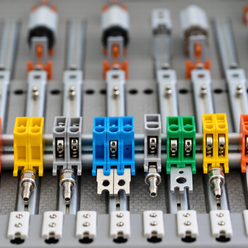
Wire terminal blocks are insulated connectors that join, distribute, or isolate electrical wires. Each wire enters a clamping point, while a conductive metal strip carries current across the connection. The housing reduces accidental contact and keeps wiring organized inside control cabinets. DIN-rail versions also allow quick installation and replacement.
Their operation is simple, but selection requires care. Spring-clamp blocks maintain pressure during vibration and temperature changes. Screw-clamp blocks offer familiar installation and visible tightening. Feed-through blocks connect two wires, while ground blocks bond circuits to the protective earth system. IEC 60947-7-1 defines key requirements for terminal blocks used in industrial equipment. The UL 1059 standard also addresses construction and performance criteria in North American applications.
Market demand is expanding with factory automation and renewable-energy installations. MarketsandMarkets’ Terminal Blocks Market report projects growth from about USD 4.1 billion in 2024 to nearly USD 5.5 billion by 2029. That growth does not make every terminal block suitable. I have seen oversized blocks waste cabinet space, while undersized ones create heat and maintenance risks. The choice is not always obvious.
Tips: Check rated voltage, current, wire range, and insulation temperature together. Confirm conductor material and tightening torque. Leave room for a test probe. For vibration-prone equipment, spring connections deserve serious consideration. A final pull test helps, although it is easy to overlook. Always verify the manufacturer’s technical sheet and the applicable local installation rules.
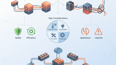
Typical compatible conductor cross-section ranges for commonly used wire terminal block formats. Actual ratings vary by design, temperature, wire material, and applicable standards.
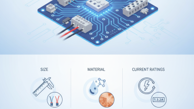
Smaller terminal blocks are commonly used for sensors and control wiring, while high-current and distribution blocks support larger conductors. Buyers should also verify rated voltage, current, insulation material, spacing, temperature range, and certification requirements.
Comparing the 10 best terminal blocks starts with measurable specifications, not appearance. A 2024 MarketsandMarkets report estimates the global terminal block market will grow from about USD 3.9 billion in 2024 to USD 5.4 billion by 2029. This growth reflects demand for safer, denser, and more serviceable wiring systems.
Rated voltage and current should match the application’s real load. Higher ratings are not automatically better. Check conductor size, temperature rise, insulation material, and tightening torque together. IEC 60947-7-1 provides a useful reference for low-voltage terminal block performance. UL 1059 is also commonly used for component evaluation in industrial applications. Look for clear test conditions, not only impressive headline values.
Mechanical details matter during installation. Compare pitch, mounting method, wire-entry direction, and the number of circuits per rail. A narrow 3.5 mm pitch saves panel space, but it can make inspection difficult. Vibration resistance, flame rating, and corrosion protection deserve equal attention in factories or outdoor cabinets. Ingress protection should match the enclosure, not merely the terminal block. According to the 2023 World Robotics report from the International Federation of Robotics, global factory robot installations reached 541,302 units in 2022, increasing demand for compact control wiring. Datasheets may still omit practical access limits. I would request sample testing before approving large-volume purchases.
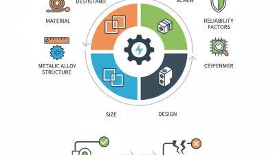
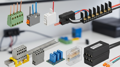
The 10 best wire terminal blocks depend on the application, conductor size, and working environment. Screw-clamp blocks suit control panels where technicians need visible, adjustable connections. Spring-clamp blocks resist vibration and reduce retightening work. Push-in blocks support faster assembly on repetitive production lines. Barrier blocks handle organized multi-wire connections in equipment with moderate movement.
DIN-rail terminal blocks are practical for industrial cabinets and clear circuit grouping. Feed-through blocks connect wires across a panel while saving space. Grounding blocks create a dependable path for protective conductors. Fuse terminal blocks combine connection and overcurrent protection in compact circuits. Disconnect blocks help technicians isolate equipment during inspection. PCB terminal blocks connect external wires to circuit boards without permanent soldering.
Check the rated voltage, current, wire range, insulation material, and temperature rating before selection. Confirm the terminal accepts solid, stranded, or ferruled conductors. Correct tightening torque matters. Too little pressure can create heat, while too much can damage the clamp. In humid areas, sealed terminal blocks may perform better, but sealing alone cannot fix poor cable preparation. A perfect choice is difficult. Field conditions often expose weaknesses that catalog data misses. Trial installation, pull testing, and periodic inspection provide more reliable results than appearance alone.
Choosing a terminal block for global use requires more than matching voltage and wire size. Field inspections show that pitch, conductor material, torque range, and temperature ratings often decide long-term reliability. A block rated for 600 V may still fail a project review if creepage, clearance, or touch protection is inadequate. Check IEC 60947-7-1, IEC 60998, and the destination market’s installation rules. Do not assume one certificate covers every country.
Market data supports careful selection. The MarketsandMarkets Terminal Blocks Market report, 2024 edition, forecasts growth from approximately USD 4.2 billion in 2024 to USD 5.6 billion by 2029, near a 6% CAGR. This expansion reflects demand for modular control panels, industrial automation, and renewable-energy equipment. For buyers, higher volume does not remove technical risk. Verify current capacity at the actual ambient temperature, not only the headline rating.
A practical review should include a sample wire, ferrule, screwdriver, and torque test. Inspect whether the clamp grips firmly without cutting strands. Compare flame resistance, vibration performance, corrosion protection, and labeling space. Standards can differ in testing methods. Some projects require recognized component evidence, while others require complete assembly verification. My own preference is to request test reports and traceable material records before ordering. It takes longer. Yet relying on a familiar catalog description can be an expensive mistake.
When comparing the 10 best wire terminal blocks for global buyers, installation details deserve close attention. A suitable block should match the wire size, conductor material, voltage, current, and available panel space. Check the datasheet before ordering. Do not rely on appearance alone. A compact terminal may look efficient but leave little room for a screwdriver or inspection. For field installation, clear markings and strong mounting rails reduce mistakes.
Safety begins with correct preparation. Strip each wire to the specified length, without cutting copper strands. Loose strands can create heat and unstable contact. Tighten screws with a calibrated torque tool when the manufacturer provides a value. Excessive force may damage the conductor or housing. Insulated ferrules can improve consistency on flexible wires, but they must fit properly. Always isolate power before installation and verify the circuit with a suitable tester.
Maintenance should be practical and repeatable. Inspect terminals for discoloration, cracked insulation, corrosion, or loose conductors. Look closely near high-load circuits. Heat marks are warnings, not decoration. Dust and moisture may also weaken connections, especially in workshops or outdoor cabinets. Use an enclosure suited to the environment, and record inspection dates and torque checks. I once treated a clean-looking panel as reliable, then found one loose wire during testing. That mistake changed my routine. Still, visual checks can miss hidden damage, so periodic electrical testing remains necessary. When selecting global products, confirm documentation, traceability, and replacement availability before installation.
| Rank | Terminal Block Type | Typical Application | Conductor Size | Typical Rated Voltage | Typical Current | Wire Entry | Recommended Torque | Operating Range | Installation Considerations | Safety and Maintenance Considerations |
|---|---|---|---|---|---|---|---|---|---|---|
| 1 | Feed-Through Screw Terminal Block | General control panels, machinery, and distribution wiring | 0.2–2.5 mm² (24–12 AWG) |
Up to 600 V | Up to 24 A | Top or side | 0.5–0.8 N·m | −40 to +105°C | Strip to the specified length, fully insert the conductor, and tighten with a calibrated screwdriver. | Use an end plate and separator where required. Recheck torque after initial thermal cycling and inspect for discoloration or loose strands. |
| 2 | High-Current Feed-Through Terminal Block | Motor feeders, power supplies, and industrial control cabinets | 1.5–6 mm² (16–10 AWG) |
Up to 800 V | Up to 41 A | Top or side | 0.8–1.2 N·m | −40 to +105°C | Confirm the conductor cross-section, ferrule compatibility, and the terminal's permissible jumper system before wiring. | Keep power and signal circuits separated. Check temperature rise under maximum load and retighten only to the specified torque. |
| 3 | Push-In Spring Terminal Block | Vibration-prone equipment and rapid panel assembly | 0.2–2.5 mm² (24–12 AWG) |
Up to 800 V | Up to 24 A | Top | Tool-free | −40 to +105°C | Use solid or correctly prepared stranded wire. Operate the release lever or push button when removing conductors. | Verify that the conductor is fully seated by performing a gentle pull test. Inspect spring openings for dust, debris, or damaged insulation. |
| 4 | Double-Level Terminal Block | High-density PLC, I/O, and instrumentation panels | 0.2–2.5 mm² (24–12 AWG) |
Up to 500 V | Up to 20 A | Top | 0.4–0.6 N·m | −40 to +105°C | Leave adequate clearance for test probes and screwdrivers; clearly label both levels to prevent cross-connection. | Do not exceed the derated current when both levels are loaded. Check insulation barriers and terminal identification during maintenance. |
| 5 | Protective Earth (PE) Terminal Block | Protective bonding of metal enclosures and DIN rails | 0.2–6 mm² (24–10 AWG) |
Voltage not primary rating | Up to 41 A (application-dependent) |
Top or side | 0.5–1.2 N·m | −40 to +105°C | Mount on the specified conductive DIN rail or bonding surface and ensure paint does not interrupt the earth path. | Test continuity and protective bonding according to local electrical regulations. Look for corrosion, oxidation, and loose protective conductors. |
| 6 | Disconnect or Test Terminal Block | Measurement circuits, sensors, and commissioning points | 0.2–2.5 mm² (24–12 AWG) |
Up to 500 V | Up to 20 A | Top | 0.4–0.6 N·m | −40 to +105°C | Install the disconnect link in the correct position and provide test plugs or test sockets where required. | Open circuits only under permitted load conditions. Label test points and inspect links for wear, contamination, or accidental displacement. |
| 7 | Fuse Terminal Block | Branch-circuit protection for control and instrumentation wiring | 0.2–2.5 mm² (24–12 AWG) |
Up to 500 V | Up to 6.3 A fuse-dependent |
Top | 0.4–0.6 N·m | −40 to +85°C | Install only the specified fuse size and type. Maintain separation from adjacent live circuits and provide clear circuit identification. | Isolate power before fuse replacement unless the design specifically permits live servicing. Check fuse clips for heat damage and oxidation. |
| 8 | Neutral Disconnect Terminal Block | Single-phase distribution and serviceable neutral circuits | 0.5–6 mm² (20–10 AWG) |
Up to 600 V | Up to 32 A | Top or side | 0.6–1.2 N·m | −40 to +105°C | Observe local rules for neutral conductors, use the correct jumper accessories, and avoid mixing neutral and protective-earth functions. | Mark the neutral circuit clearly. Verify isolation with an approved tester and inspect the disconnect mechanism during scheduled service. |
| 9 | Barrier Screw Terminal Block | Power distribution, transformers, HVAC, and equipment wiring | 0.5–6 mm² (20–10 AWG) |
Up to 300 V | Up to 30 A | Side | 0.8–1.2 N·m | −25 to +85°C | Use the correct wire entry, avoid excessive stripping, and fit a cover when exposed terminals could be touched. | Keep each conductor under its permitted clamp capacity. Inspect screws, barriers, and housing for cracking or heat-related deformation. |
| 10 | High-Temperature Ceramic Terminal Block | Heating equipment, ovens, lighting, and elevated-temperature enclosures | 0.5–4 mm² (20–12 AWG) |
Up to 450 V | Up to 25 A | Side | 0.6–1.0 N·m | −40 to +200°C material-dependent |
Use heat-rated wire insulation, maintain clearance from hot surfaces, and install strain relief where vibration or thermal expansion is present. | Allow the equipment to cool before service. Inspect ceramic bodies for cracks and terminals for oxidation; verify the actual temperature rating in the datasheet. |
Note: Ratings shown are representative industry ranges for commonly used terminal-block configurations. Actual voltage, current, wire-size, torque, temperature, creepage, and certification values vary by construction and installation method. Always confirm the applicable manufacturer datasheet and local electrical code before selection or installation.